
Please Leave Us A Message
Privacy statement: Your privacy is very important to Us. Our company promises not to disclose your personal information to any external company with out your explicit permission.

A bandpass filter is a filter that can pass a frequency component in a certain frequency range but attenuate other ranges of frequency components to an extremely low level, as opposed to the concept of a bandstop filter. An example of an analog bandpass filter is a resistor-inductor-capacitor circuit (RLC circuit). These filters can also be generated using a low pass filter in combination with a high pass filter.
An ideal bandpass filter should have a completely flat passband that is not amplified or attenuated in the passband, and all frequencies outside the passband are completely attenuated. In addition, the transition outside the passband is minimal. The frequency range is complete.
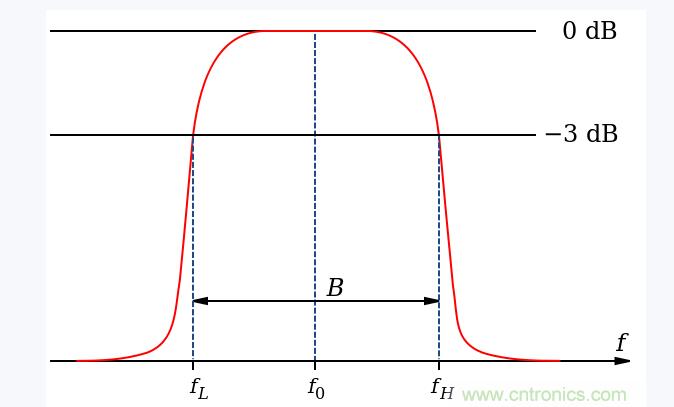
In fact, there is no ideal bandpass filter. The filter is not able to completely attenuate all frequencies outside the desired frequency range, especially outside the desired passband, with a range that is attenuated but not isolated. This is commonly referred to as the roll-off phenomenon of the filter and is expressed in dB of the attenuation amplitude per decade.
In general, the filter is designed to ensure that the roll-off range is as narrow as possible, so that the performance of the filter is closer to the design. However, as the roll-off range becomes smaller and smaller, the passband becomes flatter and begins to [ripple". This phenomenon is especially noticeable at the edges of the passband, an effect known as the Gibbs phenomenon.
In addition to electronics and signal processing, an example of a bandpass filter application is in the field of atmospheric science. A very common example is the use of a bandpass filter to filter weather data over the last 3 to 10 days, so that the data Only the cyclone that is disturbed is retained in the domain.
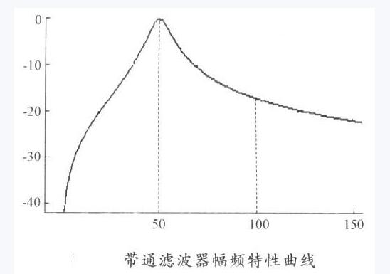
Between the lower shear frequency f1 and the higher shear frequency f2 is the resonant frequency, where the gain of the filter is the largest, and the bandwidth of the filter is the difference between f2 and f1.
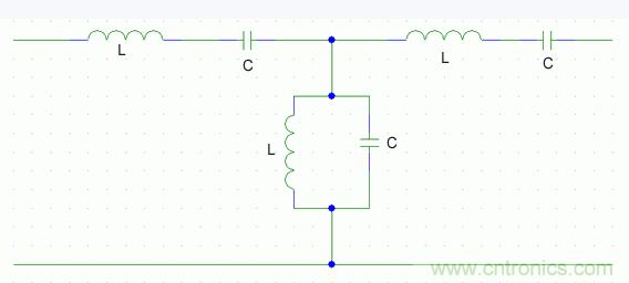
Bandpass is to pass a certain range of frequencies and filter out the remaining frequencies. For example, a high pass filter + a low pass filter can form a band pass filter. It is broadly divided into an analog bandpass filter and a digital bandpass filter. Analog bandpass filters typically use circuit components (such as resistors, capacitors, and inductors) to form the frequency characteristic circuit we need.
The principle of the analog bandpass filter is to configure the capacitance, resistance and inductance parameters so that the analog filter exhibits a small impedance to the fundamental wave and a large impedance to the harmonics, so that when the load current signal passes the simulation The fundamental signal can be extracted when the bandpass filter is used. At present, some active filters use analog circuits to implement a bandpass filter to detect the fundamental component of the load current, and have been applied in practice.
However, analog bandpass filters also have some of their own drawbacks. This is because the center frequency of the analog filter is very sensitive to the parameters of the circuit components (such as capacitors, resistors, and inductors). It is difficult to design suitable parameters, and the parameters of the circuit components will change with the interference of the external environment, which will result in The offset of the center frequency affects the accuracy of the filtering results.
The digital bandpass filter uses software to implement the above filtering process, which can well overcome the shortcomings of the analog filter. Once the parameters of the digital bandpass filter are determined, there will be no change, as long as the fluctuation frequency of the grid is designed in our design. Within the scope of the range, the fundamental component can be extracted better. Digital filters can be classified into IR type and FIR type according to their types. The PIR type has only zero point, and it is not easy to obtain better passband and stopband characteristics like the IR type.
Therefore, the IR type is selected in the general design. The IR type can be further divided into a Butterworth type filter, a Chebyshev type filter, a Chcbyshev type I filter, and an elliptical type filter.
In fact, the bandpass filtering we usually say is to pass within the specified frequency range.
1, high pass filter + low pass filter = band pass filter
2, high resistance filter + low resistance filter = band pass filter
For example: 600H-----5KHZ bandpass filter
First make a 600HZ high-pass filter, and then make a 5KHZ low-pass filter to filter the frequency through 600NZ in the high-pass filter, and then filter out the frequency above 5KHZ through the low-pass filter. 600 H----- 5KH Z frequency. The principle of high-impedance filter + low-impedance filter = band-pass filter is the same.
LET'S GET IN TOUCH
Privacy statement: Your privacy is very important to Us. Our company promises not to disclose your personal information to any external company with out your explicit permission.
Fill in more information so that we can get in touch with you faster
Privacy statement: Your privacy is very important to Us. Our company promises not to disclose your personal information to any external company with out your explicit permission.