
Please Leave Us A Message
Privacy statement: Your privacy is very important to Us. Our company promises not to disclose your personal information to any external company with out your explicit permission.

The optical component is a very precise component, and the manufacturing cost is high. If the thickness of the component can be reduced, or even a sheet lens, the size of the optical component can be reduced, thereby reducing the size of the lamp or other equipment, and saving material. cut costs. As the thickness is reduced, the light absorption is also reduced, and the efficiency of the luminaire or instrument is also increased. Therefore, it is one of the goals of optical design to make high-quality sheet-shaped optical parts.
The Fresnel lens is a sheet-like thin lens that has been used in some aspects for its lightness, thinness and low cost. However, the Fresnel lens on the market is mostly concentric circle structure with equal radius. The fabrication lacks precise optical design process, resulting in low image quality, and some even simple corrugated structures, and its optical quality is even worse. . Even a better Fresnel lens is usually formed by dividing a common lens into small segments, which are approximately broken lines, and are formed by simple translation of different distances. The defects in these design methods result in low quality of the Fresnel lens.
LEDs are small in size, but most of the LED lenses on the market are thicker than 10mm, which is a fatal problem for LEDs in some applications, although Fresnel lenses can be used to reduce the thickness of the lens and reduce light absorption. However, how to carry out accurate optical design is rarely reported in the literature.
This article describes the design method for obtaining accurate ultra-thin zigzag lenses with good optical quality and high light utilization. Because the general Fresnel lens is theoretically wasteful, that is, the light passing through the lens theoretically has a part that cannot reach the destination of the design, and the lens obtained by the method has no theoretical waste. In addition, the distance between the small serrations can also be different according to needs, and the zigzag spacing at different positions in the same lens can also be changed, so that the zigzag lens designed by this method has wider adaptability, that is, it can Adapt to different conditions of use and different processing conditions.
This zigzag lens is suitable for secondary optical lenses in which the LED is a light source. For a small-sized light source such as an LED, it is very meaningful to have a small and thin Optical Lens.
First, the design principle
A single lens is generally a transparent material whose surface shape is curved, and its function is to change the direction of the light to form a desired spatial distribution of light intensity. The disadvantage is that it tends to be relatively thick, so it is bulky and costly, and the absorption is large, especially for lenses with large curvature. For the sake of simplicity, an example of a plano-convex lens is shown in Fig. 1(a). Correspondingly, the conventional Fresnel lens is shown in Fig. 1(b). For the sake of explanation, the pitch of the figure is relatively large.

Figure 1 The formation principle of the traditional Fresnel lens
The design principle of Fresnel lens is to replace the entire continuous large surface with several small faces. Figure 1 (c) shows the design principle of a conventional Fresnel lens. The function of the sawtooth Fresnel lens of Fig. 1(b) is the same as that of the original lens of Fig. 1(a). The traditional design method can be represented by Figure 1 (c). Actually, the Fresnel lens of Fig. 1(b) can be regarded as that a plurality of rectangular portions are deleted from the lens of Fig. 1(a), and the remaining portion is moved downward into a sheet shape to become a Fresnel lens. See Figure 1(c), where the stepped shadow is the part of the multiple rectangles that are deleted.
It is obvious that the Fresnel lens of Fig. 1(b) is thinner than the lens (a), so that the absorption is small and the material is saved. However, this conventionally designed lens is correct only for parallel light, in which case the shaded portion of (c) has no effect on the light. However, in the case of non-parallel light, such as when the LED is a light source, the shaded portion of (c) has an effect on the light. If it is removed into a Fresnel lens, it will cause a lot of stray light. In addition, if the cross section of the lens is replaced by a broken line instead of a small arc, an optical error will also occur.
In order to overcome the above shortcomings, we propose to design Fresnel lenses in two new ways. Here we design for a single LED. For other light sources, the design principle is the same, so in principle it can be extended to other light sources.
The basic idea of the new method is to divide the edge of the deleted invalid part along the light, and the effective remaining part moves along the light while changing its size in a certain proportion, so that the light will not propagate in the lens. Hit the invalid part of the edge and it will be refracted in the original direction. This reduces the scattered light and increases the optical efficiency of the lens.
Second, the design method
1, the angle method

Figure 2 angle method
We assume that the incident surface of the original lens is a plane, and the exit surface (the surface on which AB is located in Figure 2) is a curved surface. As for how to design the original surface, it is beyond the scope of this article. The new exit surface is the zigzag we want to design.
In this paper, we can assume that the O point is the position of the virtual image point after the light source passes through the incident surface, that is, the light from the O point passes through the exit surface and reaches the image surface (the lens may not be "imaged" but illuminated). So we will include the role of the entrance surface. We can divide the surface where AB is located into small segments at the angle of the point O. In the figure, AB is one of the small segments. Instead of moving these small segments vertically as in the first section, we moved them in the direction of the light and scaled them while scaling. Thus, AB is scaled to A'B'. According to the principle of linear optics, the direction of light refraction caused by facet A'B' is exactly the same as that of facet AB, except that the position of the light is slightly different. Since the lens size is much smaller than the image distance, and the distance difference between OA and OA' is a second-order small amount, we can only care about the angle of the outgoing light before and after the design without concern for the position of the light. Minor changes, that is to say the facets before and after the change, will not make a significant difference in the optical effect of the entire lens, especially for illumination lenses.
In addition, the division of the angles may be equal or unequal, and neither of these cases affects the optical effect. To illustrate the problem, Figure 2 only divides the lens into 8 parts. In fact, the larger the number of divisions, the thinner the lens can be. However, as mentioned below, a larger number will bring new problems.
However, it can be seen that one disadvantage of the above method is that the sawtooth thickness of the lens will be different, which may affect the strength of the lens. Another method is proposed below, which can achieve the same thickness of the sawtooth. Although the design process is more complicated, it can not only overcome the problem of uneven thickness, but also eliminate stray light.
2, thickness method
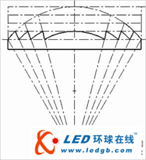
Figure 3 thickness method
3 is the same as the original lens of FIG. 2, but in FIG. 3, the original lens is divided into several parts in the thickness direction by equal distance (see the horizontal dotted line of FIG. 3), and then the same method is used in the upper section angle method. Each segment is linearly reduced while moving along the light to form a lens of substantially the same thickness.
This method not only achieves the same sawtooth depth, but also increases the strength of the lens, and can reduce the thickness at the same number of teeth compared to the angle-angle method, or reduce the number of saw teeth at the same thickness. It can be seen from the analysis below that this result can also reduce stray light of the lens, thereby improving image quality and light utilization efficiency.
It should also be pointed out that in general, as long as one of the two faces of the incident and outgoing faces is made into a serrated surface, the design requirements can be met. If the entrance surface is desired to be a sawtooth surface and the exit surface is flat, the above analysis is the same. For example, the outer surface can be a smooth surface and the inner surface can be a serrated surface, which prevents dust from accumulating. More importantly, if the side of the sawtooth is not a flat surface but a curved surface, the result is the same. In this way, we can not only make a flat-plate Fresnel lens, but also other Fresnel lenses such as curved tiles or bowls.
Third, stray light analysis
It can be seen from the analysis below that the sawtooth lens designed by the new method not only retains the advantages of the original method, but also reduces the stray light caused by the machining error.
Because in the actual processing, the tip and bottom of the sawtooth can not be infinitely small, but have a certain rounded corner, this rounded corner will affect the light can not reach the place that should be reached, causing stray light. Figure 4 is a simulation result of a single sawtooth stray light.

Figure 4 Simulation results of a single sawtooth stray light
The amount of stray light is related to the accuracy of the processing. Assuming that the average width of the sawtooth is d, the radius of the corner of the sawtooth tip is r, and it is roughly assumed that the light in the r range becomes stray light, and the ratio of light loss is r/d. For example, the sawtooth width is 1 mm, and the machining accuracy is caused. Some r is 0.05mm, the light loss is 5%. This is the light loss that the Fresnel lens has to have, which is also a disadvantage of the Fresnel lens.
However, compared to Fresnel lenses designed by other methods, the new method and other thickness methods can relatively reduce this loss. The reason for this is that the equal thickness method can have fewer sawtooth numbers under the same thickness conditions as compared with other methods, so that the average width d is larger, r/d is relatively smaller, and thus light loss is less.
Further analysis knows that since the LED light source has a large luminous intensity in the optical axis portion and a small edge portion, the thickness obtained by the thickness method has a larger pitch in the middle portion than in the edge portion (see Fig. 3). There is less loss in places where the light intensity is high, that is, there can be less light loss overall.

Figure 5 Example of two Fresnel lenses
A three-dimensional lens can be obtained by rotating or stretching the designed section. Figure 5 is an example of two Fresnel lenses. The stretched (a) can be used for a strip spot, and the rotated (b) can be used for a circular spot.
The design method uses a method of dividing the ideal optical surface and moving in the direction of the light while scaling, while maintaining the optical performance of the lens while minimizing the optical loss, and achieving higher efficiency than other methods. The method can obtain good effects on an LED light source with a small light source scale.
LET'S GET IN TOUCH
Privacy statement: Your privacy is very important to Us. Our company promises not to disclose your personal information to any external company with out your explicit permission.
Fill in more information so that we can get in touch with you faster
Privacy statement: Your privacy is very important to Us. Our company promises not to disclose your personal information to any external company with out your explicit permission.